Zimmers.NET Files (formerly ftp.funet.fi)

/pub/cbm/schematics/computers/c128/


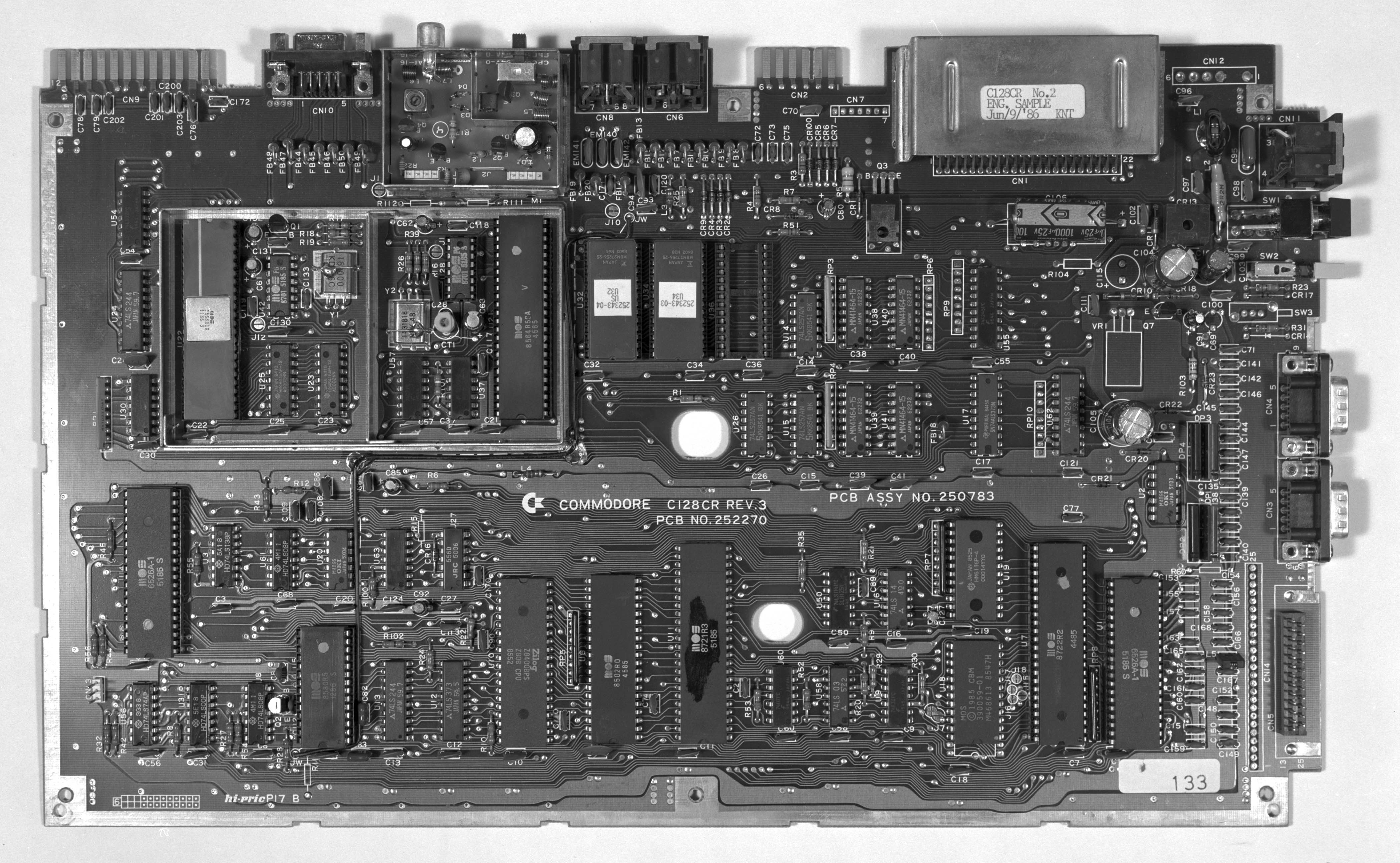
The Commodore 128 existed in three different major board versions: The first board was used in the flat 128 and in the plastic-cased 128D. Then came the 128DCR board, with the floppy controller integrated on the motherboard. There was also a 128CR (cost-reduced flat 128).

Subdirectories

drives@
Disk drives
firmware@
System firmware
power/
Power supply schematics
servicemanuals/
Service Manuals for C128-based computers

Files

310378-1-left-and-right.gif 2024-01-22 234874
310378-2-left-and-right-7a.gif 2024-01-22 310087
310378-2-left-and-right.gif 2024-01-22 211264
310378-3-left-and-right-7a.gif 2024-01-22 269038
310378-3-left-and-right.gif 2024-01-22 212042
310378-4-left-and-right.gif 2024-01-22 187857
These are the schematic diagrams of the Commodore 128 main board
("flat C128" and C128D in plastic case). They were on eight pages
in the Commodore 128 Programmer's Reference Guide, two pages
containing one engineering sheet.

310378-update.zip 1998-05-15 747229
Update to the Commodore 128 Service Manual, containing the two revised
pages in the 310378 schematic revision 7A.

8721-pla.v 2022-01-05 10319
8721 PLA in Verilog by Johan Grip

c128cr.jpg 2000-02-23 1115174
A black&white picture of a cost-reduced flat Commodore 128 circuit board.
This model never entered mass production; this is an engineering sample
possessed by Raymond Carlsen. The board says "PCB ASSY NO. 250783",
"C= commodore C128CR REV.3", "PCB NO. 252270", and "C128CR No.2
ENG. SAMPLE Jun/9/'86 KNT".

c128dcr-1-left_and_right.gif 2024-01-22 270044
c128dcr-2-left_and_right.gif 2024-01-22 298214
c128dcr-3-left_and_right.gif 2024-01-22 264840
c128dcr-4-left_and_right.gif 2024-01-22 126626
c128dcr-5-left_and_right_corrected.gif 2020-10-19 2128158
These are the schematic diagrams of the Commodore 128DCR main board
(metal case C128D with built-in 1571CR floppy controller). The diagrams
were scanned from a 64'er Sonderheft, and they appear to be a copy of
schematic 252451.

According to Nicolas Welte, there is an error on the right half of page 5.
The 74LS14 hex Schmitt-trigger inverter U113, pin 13 is connected to WPRT*
(misprinted WTRT* on U105), which doesn't make any sense. Obviously it
should be connected to STP1 instead, which is three lines more to the right!

c128schematic.gif 2018-05-17 752001
C128 schematic, unknown rev, drawn by unknown author.

mainboardC128_rev7.png 2019-11-04 12004815
Hi-res picture of 128 main board traces, without chips.

parts.txt 2015-07-08 1830
Parts list for Commodore 128, from William Levak

Mirror sitesGeneral informationFile typesData transfer